
Hello, and thank you for choosing VSP for your ground wiring DIY provider.
I know there is already a grounding write-up on here, but this one is a little different because in addition to covering the basics of replacing your three major body grounding wires, it includes instructions on how to upgrade the battery-to-fusebox and battery-to-ignition wires.
This is not a difficult job but it does require some time, a few specific tools, and a bit of patience. If case you don't have any of the tools listed, I encourage you to purchase or borrow them. Using the correct tool for a specific application will always save you lots of time, money, and headaches in the end.
*********
Tools needed:
**A Note**
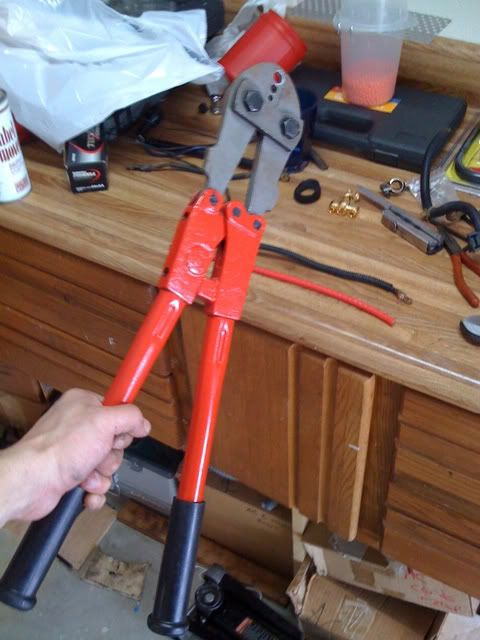
Just to repeat myself, DO NOT SKIMP ON THE TOOLS. 4-gauge crimps are no joke, and if they're not done correctly, you might as well have not done the job at all. You'll need a lot of leverage to properly set these crimps; I needed to use this aircraft crimper to get the job done:

Remember, the aim here is to duplicate or emulate stock reliability as much as possible. Shortcuts will only harm the final product; don't cheat yourself.
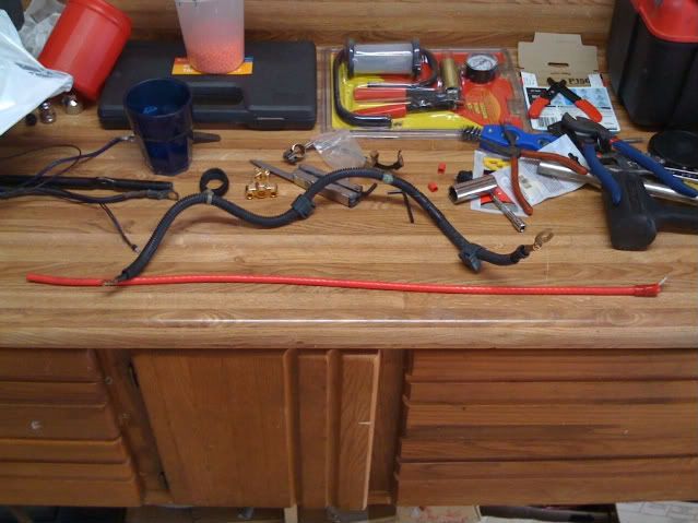
Also, this write-up is written with 4-guage wire in mind. In case you don't know, it looks like this:
Specifically, the fusebox and starter motor wires should never be replaced with anything other than this gauge of wire.
Procedure
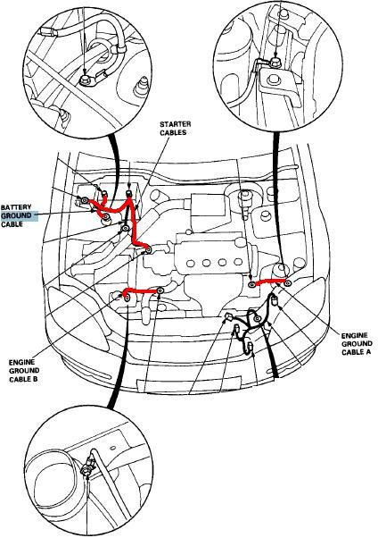
There are three major ground wires to be replaced, one ignition wire, and one fusebox wire:
The first wire to replace is the engine block-to-chassis. Unbolt the old wire using a 10mm socket:
Now, time to crimp the first cable. I HIGHLY RECOMMEND you practice this first; no worries, you'll probably get the chance either way.
How to make a replacement cable:
Using the sandpaper, sand off the paint and primer, leaving only the bare metal exposed. Make sure to do this everywhere the crimp ring touches the chassis.
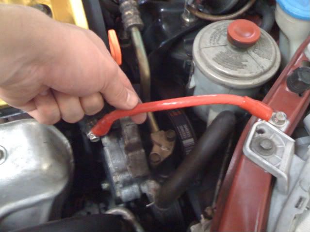
Finally, replace bolt the new wire on. Tighten the bolts until they are snug, but do not over tighten them. When you're finished it should look like this:
Next, on to the transmission-to-chassis wire.
Just like before, remove the old wire using a 10mm socket and the above diagram as reference. (Sorry, no picture of the old wire in place.)
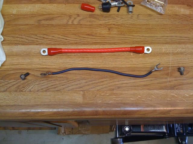
Follow the cable-making instructions from before, and you should end up with this:
Don't forget to sand down the areas the wire will bolt back down. The finished product with the new cable in place will look something like this:
The last cable is very short; it is the battery-to-chassis wire. Just like before, remove the 10mm bolt and make the new cable. One end of the wire gets a crimp, and the other will attach to the new battery terminal. In my case, it looked like this:
The final product when re-attached to the body will look like this:
This is all for the basic ground upgrades! Now that you know the basics of 4-gauge cable making, you can get all crazy if you want and start adding grounds to just about anything in your engine bay. I don't recommend it, but I know it's a popular thing to do with the pre-made grounding kits. It's up to you. This is also the time to use a multimeter to check for continuity between the negative battery terminal and your new grounding points. Or, if you don't have a fancy-shmancy $10 Radio Shack digital multimeter and are currently rocking an old-school analog unit, test for zero ohms between the aforementioned points.
Now, let's take it one step further: replacing the battery-to-fusebox wire and the battery-to-starter motor wire.
Why replace these wires? After all, they're already 4-gauge, just like what we'll be replacing them with.
The main reason is for consistency. I wanted my engine bay to look more uniform with the wiring upgrades. Another good reason would be to replace worn wire ends at the battery positive terminal; over time it's common for corrosion to wear down the conductive surface at the battery, introducing unwanted resistance and resulting in reduced electron flow capacity (current).
In my case, for example, corrosion issues had caused the wires at my battery's positive terminal to completely break off a few years ago. This was an excuse for me to make sure everything was back together correctly.
First let's do the battery-to-fusebox wire. Start by removing the negative battery terminal, then the positive one. Then open your under-hood fusebox. There are two big wires running into the fusebox. The one that is closer to the firewall is the one you want:
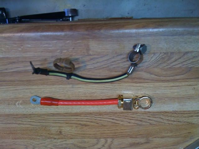
Remove the bolt with a 10mm socket and remove the old cable. Measure out and make a new cable, only crimping one end; this will go in the fusebox. Here's what the new cable should look like, and don't forget to strip back the un-crimped end for insertion into your new battery terminal:
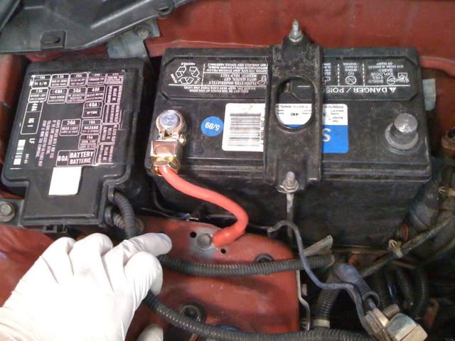
Be sure the ring crimp connector will fit in the fusebox; this is why I recommend using ones with shaved sides. Bolt down the new cable, and you're all done! Don't attach it to your battery yet, though.
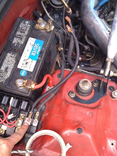
One more cable: the starter motor cable. Trace the other wire that was attached to the positive wire back to the starter motor. The wire is attached to a bracket on the passenger side shock tower with little plastic clips. Use the needle nosed pliers to carefully undo them from the bracket.
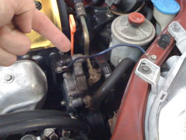
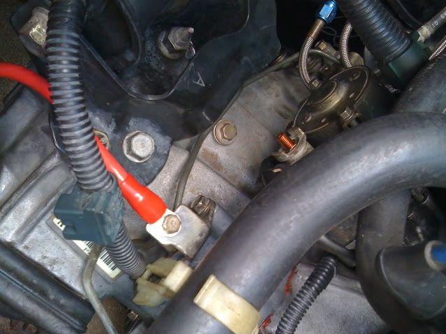
There is a rubber cover on the nut that is holding the cable to the starter motor; pull it back and remove the nut with the 12mm socket. Here is a picture of the post with the nut and wire removed, it's almost a bright orange (brass colored):
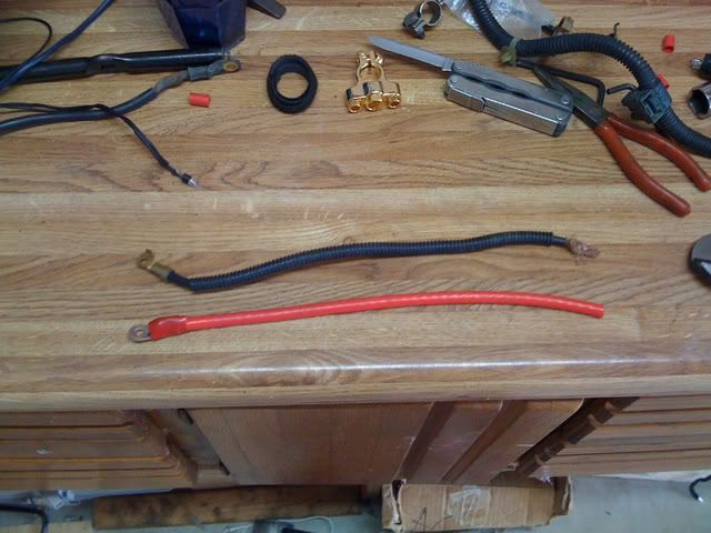
Just like before, make up a replacement cable. Only crimp one end, just like the fusebox wire:
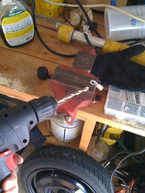
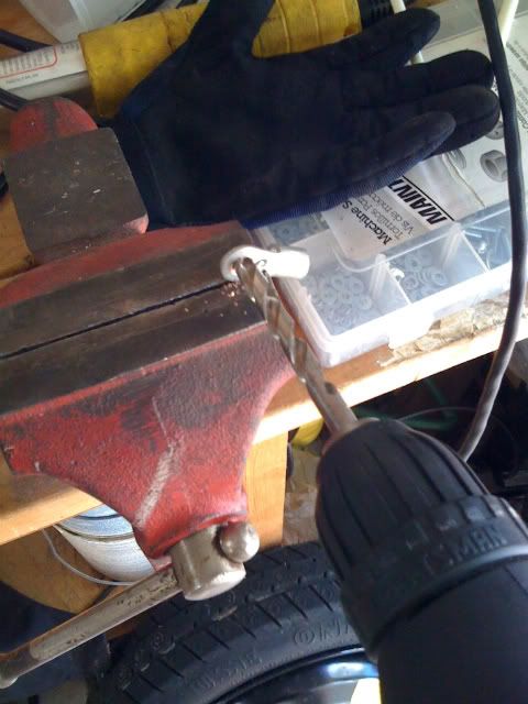
Just in case your ring crimp connectors are too small to fit over the larger starter motor's post, you can simply drill it out a bit to fit using an appropriate-sized bit. I also recommend using a vice grip to brace the crimp and prevent deforming while you drill:
Wear safety glasses when drilling anything
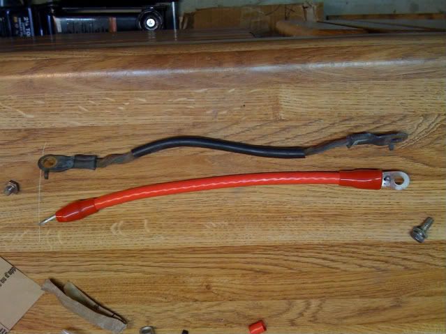
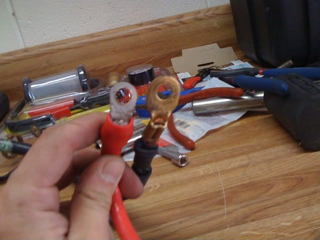
Here's the old and new connectors, for comparison:
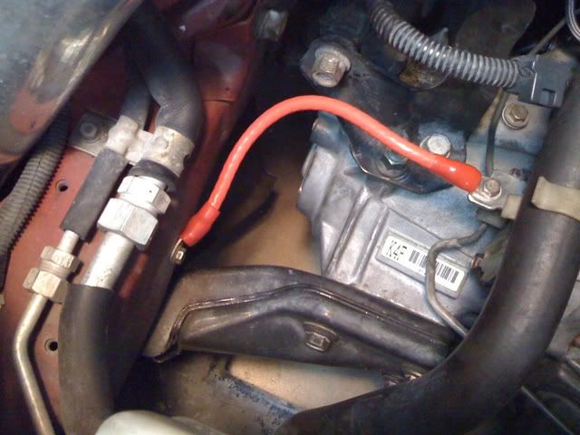
When you're done, bolt up the new wire. You may choose to use some black zip-ties to secure the new wire in place where the old one used to be.
Finally, secure the fusebox and starter motor wires to the new positive battery terminal connector. Reattach the positive terminal to the battery, then the negative terminal. When you're done, it should look something like this:
This concludes the DIY. Please post your questions, comments, edits, or concerns, and good luck!
I know there is already a grounding write-up on here, but this one is a little different because in addition to covering the basics of replacing your three major body grounding wires, it includes instructions on how to upgrade the battery-to-fusebox and battery-to-ignition wires.
This is not a difficult job but it does require some time, a few specific tools, and a bit of patience. If case you don't have any of the tools listed, I encourage you to purchase or borrow them. Using the correct tool for a specific application will always save you lots of time, money, and headaches in the end.
*********
Tools needed:
- 4-gauge cable crimper
- heavy duty cable cutters
- socket wrench
- 10mm socket
- 12mm socket
- crescent wrench (for battery terminals)
- tools for aftermarket battery terminal
- 200-grit sandpaper
- 4-gauge cable stripper
- needle-nosed pliers
- (optional, but highly recommended) multimeter to test finished connections for continuity
- (optional) drill and bits (may be needed to widen eyehole of crimp connector for starter motor fitting)
- 12 feet of 4-gauge (AWG) stranded wire
- 2 aftermarket battery terminals (positive and negative terminals, and must be capable of holding large wires)
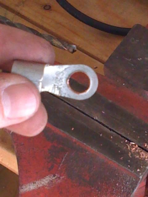
- 10 4-gauge ring [roughly 1/4"-3/8" diameter] crimp terminals (look at pictures for examples; I recommend the ones with shaved sides)
- (optional, but recommended) insulating rubber covers to protect crimps (see pictures)
**A Note**
Just to repeat myself, DO NOT SKIMP ON THE TOOLS. 4-gauge crimps are no joke, and if they're not done correctly, you might as well have not done the job at all. You'll need a lot of leverage to properly set these crimps; I needed to use this aircraft crimper to get the job done:
Remember, the aim here is to duplicate or emulate stock reliability as much as possible. Shortcuts will only harm the final product; don't cheat yourself.
Also, this write-up is written with 4-guage wire in mind. In case you don't know, it looks like this:
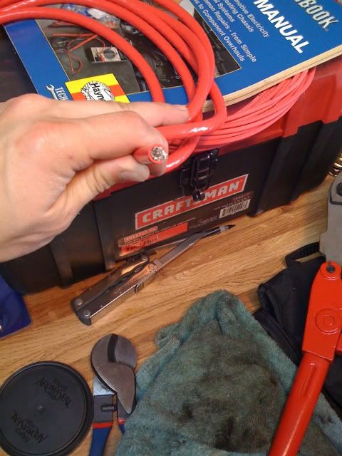
Specifically, the fusebox and starter motor wires should never be replaced with anything other than this gauge of wire.
Procedure
There are three major ground wires to be replaced, one ignition wire, and one fusebox wire:
The first wire to replace is the engine block-to-chassis. Unbolt the old wire using a 10mm socket:
Now, time to crimp the first cable. I HIGHLY RECOMMEND you practice this first; no worries, you'll probably get the chance either way.
How to make a replacement cable:
- cut new 4-gauge cable to match length of old wire
- use the wire stripper to clear about 1/2-inch of insulation off of both ends of the new cable. IMPORTAINT: DO NOT NICK or DAMAGE THE NEW WIRES OR THE CONDUCTIVITY WILL BE AFFECTED. Check each one carefully. If you damage the cable during the stripping process, cut a new cable and start over.
- insert rubber crimp protectors over each end
- insert the ring crimp over one end
- crimp down the connector in the middle of the crimp, then do the inside, then the outside. Make it tight. Do this to each end as needed.
Using the sandpaper, sand off the paint and primer, leaving only the bare metal exposed. Make sure to do this everywhere the crimp ring touches the chassis.
Finally, replace bolt the new wire on. Tighten the bolts until they are snug, but do not over tighten them. When you're finished it should look like this:
Next, on to the transmission-to-chassis wire.
Just like before, remove the old wire using a 10mm socket and the above diagram as reference. (Sorry, no picture of the old wire in place.)
Follow the cable-making instructions from before, and you should end up with this:
Don't forget to sand down the areas the wire will bolt back down. The finished product with the new cable in place will look something like this:
The last cable is very short; it is the battery-to-chassis wire. Just like before, remove the 10mm bolt and make the new cable. One end of the wire gets a crimp, and the other will attach to the new battery terminal. In my case, it looked like this:
The final product when re-attached to the body will look like this:
This is all for the basic ground upgrades! Now that you know the basics of 4-gauge cable making, you can get all crazy if you want and start adding grounds to just about anything in your engine bay. I don't recommend it, but I know it's a popular thing to do with the pre-made grounding kits. It's up to you. This is also the time to use a multimeter to check for continuity between the negative battery terminal and your new grounding points. Or, if you don't have a fancy-shmancy $10 Radio Shack digital multimeter and are currently rocking an old-school analog unit, test for zero ohms between the aforementioned points.
Now, let's take it one step further: replacing the battery-to-fusebox wire and the battery-to-starter motor wire.
Why replace these wires? After all, they're already 4-gauge, just like what we'll be replacing them with.
The main reason is for consistency. I wanted my engine bay to look more uniform with the wiring upgrades. Another good reason would be to replace worn wire ends at the battery positive terminal; over time it's common for corrosion to wear down the conductive surface at the battery, introducing unwanted resistance and resulting in reduced electron flow capacity (current).
In my case, for example, corrosion issues had caused the wires at my battery's positive terminal to completely break off a few years ago. This was an excuse for me to make sure everything was back together correctly.
First let's do the battery-to-fusebox wire. Start by removing the negative battery terminal, then the positive one. Then open your under-hood fusebox. There are two big wires running into the fusebox. The one that is closer to the firewall is the one you want:
Remove the bolt with a 10mm socket and remove the old cable. Measure out and make a new cable, only crimping one end; this will go in the fusebox. Here's what the new cable should look like, and don't forget to strip back the un-crimped end for insertion into your new battery terminal:
Be sure the ring crimp connector will fit in the fusebox; this is why I recommend using ones with shaved sides. Bolt down the new cable, and you're all done! Don't attach it to your battery yet, though.
One more cable: the starter motor cable. Trace the other wire that was attached to the positive wire back to the starter motor. The wire is attached to a bracket on the passenger side shock tower with little plastic clips. Use the needle nosed pliers to carefully undo them from the bracket.
There is a rubber cover on the nut that is holding the cable to the starter motor; pull it back and remove the nut with the 12mm socket. Here is a picture of the post with the nut and wire removed, it's almost a bright orange (brass colored):
Just like before, make up a replacement cable. Only crimp one end, just like the fusebox wire:
Just in case your ring crimp connectors are too small to fit over the larger starter motor's post, you can simply drill it out a bit to fit using an appropriate-sized bit. I also recommend using a vice grip to brace the crimp and prevent deforming while you drill:
Wear safety glasses when drilling anything
Here's the old and new connectors, for comparison:
When you're done, bolt up the new wire. You may choose to use some black zip-ties to secure the new wire in place where the old one used to be.
Finally, secure the fusebox and starter motor wires to the new positive battery terminal connector. Reattach the positive terminal to the battery, then the negative terminal. When you're done, it should look something like this:

This concludes the DIY. Please post your questions, comments, edits, or concerns, and good luck!
 might have to do this. ive got a roll of wire and a box of crimp connectors lying around the garage.