Rally Style Hella 500 Driving Lights
The Rally Style Hella 500 Driving Light System "How To" Installation Guide for 99-00 Civics
I apologize but this is NOT the full version of the install. Email me for the full version in M.S. Word format.
Wildwilliam20@gmail.com or PM me
Step 1: Getting Started
Your Hella 500 driving light kit should have included a 4 prong relay and a 2 or 3 prong switch along with the appropriate wiring necessary to complete the installation of 1 set of lights. For this project 2 sets of lights were installed and both relays and switches were utilized. This is where you may choose to be diverse. One relay and one switch can be used to activate both sets of driving lights with some amateur wiring techniques.
Your lights should already have H3 bulbs installed in each one but the ground wires that ground each light have not yet been installed. With a Philips head screw driver dismantle each light and attach the blue ground wires provided with the kit to each light and run the wire through the case. Each light came with a small black rubber plug that fits a ½” hole in the case. Put small slits in the face of each plug so you can pull the wires through. This plug is to water-proof the lights. Now put the lights back together and pull out the wire’s slack through the plug, you don’t want the wires touching the inside of the light.
Step 2: Mounting the Relay(s) and Switch(s)
Find a suitable location for the relay boxes. A good location is on the passenger side near the stock air box’s compartment of the engine bay (see picture 1). With self-tapping screws and your power-drill with a Philips head bit screw the first screw into its location. Now with a measuring tape align the location for your next self-tapping screw being sure that there is space between them for the relay boxes to sit side-by-side (too close and you'll be making a 3rd hole, not fun). Remove the screws after they’ve made their holes and mount the relays. Now you should mount the switches. I recommend mounting on the driver side plastic under-dash near your factory coin holder. Use the 1/2" drill bit to make 2 holes in the panel.
Step 3: Wiring the Relay(s) to the Switch(s)
Disconnect both battery terminals, negative first. Unbolt the battery tie down and remove the battery. Now unbolt the battery support plate and detach the zip-tie-plugs connected too it and remove the plate. Here you should see a steel line running into the firewall through a rubber "plug". You need to make a small slit in this rubber piece to allow wires to be run from the engine bay to the cabin. While inside the passenger side of the cabin remove the ECU's protective plastic cover located to the right of the foot resting area. Remove passenger side floor mat and pull carpet back towards passenger seat revealing the firewall and thus the newly made entrance for wires. Run the 2 wires included in the kit through the firewall and into the cabin, then behind the dash up to the driver side. With enough slack in the wire for them to reach your switch location zip-tie the wires to other factory wires to keep them from dangling.
These switches will need a control wire (provides a signal that allows the switches to cut on the lights or not, similar to an amplifiers control wire). This can be an "always on" source or a conditioned source. Now is the time to either run 2 more wires (not provided) through your firewall entrance for an "always on" wire or find a power source inside the vehicle's cabin for a "conditional" wire such as your CD player's power source or similar power source (headlight low/beam or high/beam wire). **Hella recommends connecting your control wire to the headlight's high/beam power wire. This is because these lights cannot legally be on if your low/beam lights are on, only when the high/beams are on are these driving lights legal but what fun is that?** I suggest using the "always on" source meaning to connect this wire DIRECTLY to your battery so that your driving lights can be activated under any circumstance, BUT I also recommend using a safety style switch so that your lights cannot be accidentally turned on and left on while the vehicle is off (see picture 3)!
When you have run these wires through the firewall you can replace the battery support plate, reconnect the zip-tie clips to it, and replace the battery and tie downs. Don’t reconnect the terminals just yet. Push the passenger side carpet back into place and re-attach the ECU’s protective plastic cover.
The relays need to be grounded. I recommend grounding them to the passenger side shock tower (see picture 1) because this location is really close to the relays and easily accessible.
Step 4: Fabricating the Mounting Bar
Here is the fun part but read carefully. First off you need to cut your mounting bar to a suitable size: the lights are 6.5” in diameter, ideally you want .25” of gap between them so if 4 lights are going to be mounted then the minimum width of your setup should be 26.75”. Actually though, because the lights are mounted from the center of their diameter the mounting bar does not need to be this long, though do not cut it shorter than 22”. Basically the bar should be between 22” and 27”.
With your mounting bar cut to length it is time to drill your 4 holes. As before said the lights are 6.5” in diameter with .25” between them. Thinking logically your first hole should be centered .875” from the bar’s edge IF your bar is 22” long, or 1.875” from the edge if your bar is 24” long, get it? This first hole does NOT have to be perfect so long as each hole drilled next is centered 6.75” away from the previous hole (see picture 4).
With a pilot drill bit, start a small hole at the predetermined distance from the edge and be sure it is centered on the surface of the bar. If this hole is too close to the vertical surface of the bar you will not be able to fit a socket over the nut to tighten down the bolt! Gradually increase the size of your drill bits to widen the hole until you have a ½” hole drilled. Take a ½” bolt from the light kit and test it in the hole, you may need to slightly widen the hole so the bolt can pass through. With your measuring tape measure from the CENTER of this first hole a length of 6.75” and make a small mark with a pencil or marker. This is the location for your next hole. Repeat the drilling process for hole number 2, then again for 3 and 4. Once all the holes are finished mount the 4 lights on the bar, tighten the bolts snug so that you can still rotate the lights on the bar with your hands. This is so you can aim the lights later.
Step 5: Removing the Front Bumper
This is perhaps the easiest and quickest step. First turn the wheels either direction so you have space to reach your hand into the fender-well. There is 1 screw on either side of the bumper in the upper corners; these hold the bumper to the fender. Remove these screws. Now there are 7 clips on the upper grille that hold the bumper to the frame. With a flat head screw driver remove these clips. You do not need to completely remove the bumper from the car. Pull the bumper forward making sure the corners aren’t caught on the fenders and then let the bumper hang down (see picture 5).
Step 6: Mounting the Lights to the Frame
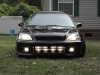
This is actually a fairly easy step thanks to your power drill with Philips head attachment and your self tapping screws (see picture 6). First, with your measuring tape find the exact middle of your mounting bar and with a marker put a small mark. Now find the exact middle of the frame that you will be attaching everything to. It would help to have an assistant now. Hold the mounting bar up to the frame and line up the two marks that you made then begin putting in the first screw into a suitable location through the bar and into the frame (see picture 7). Don’t tighten the screw down all the way yet. Carefully level the mounting bar parallel with the frame then put another screw in on the opposite end of the bar. Evenly space 4 or more screws into the mounting bar starting closest to the center then work your way to the ends and tighten them all (see picture 8).
Step 7: Wiring the Lights for Power and Ground
The blue wires that lead out of the lights themselves are ground wires and short ones at that. I recommend creating larger diameter ground wires to ground 2 lights onto 1 wire (see picture 9). You can use the supplied battery terminal wire ends and your crimpers for this. Connect the blue grounds to the lights and to the relay.
Next is time to run the power wires. Find a route to run the long black power wires from your relays to the lights. Depending on which lights you connect the wires to will change which switch activates a set of lights. I recommend connecting the two inner lights to relay “A” and the outer lights to relay “B”. Use zip-ties to secure the wires. Connect the black wires to the lights and to the relay.
The Rally Style Hella 500 Driving Light System "How To" Installation Guide for 99-00 Civics
I apologize but this is NOT the full version of the install. Email me for the full version in M.S. Word format.
Wildwilliam20@gmail.com or PM me
Step 1: Getting Started
Your Hella 500 driving light kit should have included a 4 prong relay and a 2 or 3 prong switch along with the appropriate wiring necessary to complete the installation of 1 set of lights. For this project 2 sets of lights were installed and both relays and switches were utilized. This is where you may choose to be diverse. One relay and one switch can be used to activate both sets of driving lights with some amateur wiring techniques.
Your lights should already have H3 bulbs installed in each one but the ground wires that ground each light have not yet been installed. With a Philips head screw driver dismantle each light and attach the blue ground wires provided with the kit to each light and run the wire through the case. Each light came with a small black rubber plug that fits a ½” hole in the case. Put small slits in the face of each plug so you can pull the wires through. This plug is to water-proof the lights. Now put the lights back together and pull out the wire’s slack through the plug, you don’t want the wires touching the inside of the light.
Step 2: Mounting the Relay(s) and Switch(s)
Find a suitable location for the relay boxes. A good location is on the passenger side near the stock air box’s compartment of the engine bay (see picture 1). With self-tapping screws and your power-drill with a Philips head bit screw the first screw into its location. Now with a measuring tape align the location for your next self-tapping screw being sure that there is space between them for the relay boxes to sit side-by-side (too close and you'll be making a 3rd hole, not fun). Remove the screws after they’ve made their holes and mount the relays. Now you should mount the switches. I recommend mounting on the driver side plastic under-dash near your factory coin holder. Use the 1/2" drill bit to make 2 holes in the panel.
Step 3: Wiring the Relay(s) to the Switch(s)
Disconnect both battery terminals, negative first. Unbolt the battery tie down and remove the battery. Now unbolt the battery support plate and detach the zip-tie-plugs connected too it and remove the plate. Here you should see a steel line running into the firewall through a rubber "plug". You need to make a small slit in this rubber piece to allow wires to be run from the engine bay to the cabin. While inside the passenger side of the cabin remove the ECU's protective plastic cover located to the right of the foot resting area. Remove passenger side floor mat and pull carpet back towards passenger seat revealing the firewall and thus the newly made entrance for wires. Run the 2 wires included in the kit through the firewall and into the cabin, then behind the dash up to the driver side. With enough slack in the wire for them to reach your switch location zip-tie the wires to other factory wires to keep them from dangling.
These switches will need a control wire (provides a signal that allows the switches to cut on the lights or not, similar to an amplifiers control wire). This can be an "always on" source or a conditioned source. Now is the time to either run 2 more wires (not provided) through your firewall entrance for an "always on" wire or find a power source inside the vehicle's cabin for a "conditional" wire such as your CD player's power source or similar power source (headlight low/beam or high/beam wire). **Hella recommends connecting your control wire to the headlight's high/beam power wire. This is because these lights cannot legally be on if your low/beam lights are on, only when the high/beams are on are these driving lights legal but what fun is that?** I suggest using the "always on" source meaning to connect this wire DIRECTLY to your battery so that your driving lights can be activated under any circumstance, BUT I also recommend using a safety style switch so that your lights cannot be accidentally turned on and left on while the vehicle is off (see picture 3)!
When you have run these wires through the firewall you can replace the battery support plate, reconnect the zip-tie clips to it, and replace the battery and tie downs. Don’t reconnect the terminals just yet. Push the passenger side carpet back into place and re-attach the ECU’s protective plastic cover.
The relays need to be grounded. I recommend grounding them to the passenger side shock tower (see picture 1) because this location is really close to the relays and easily accessible.
Step 4: Fabricating the Mounting Bar
Here is the fun part but read carefully. First off you need to cut your mounting bar to a suitable size: the lights are 6.5” in diameter, ideally you want .25” of gap between them so if 4 lights are going to be mounted then the minimum width of your setup should be 26.75”. Actually though, because the lights are mounted from the center of their diameter the mounting bar does not need to be this long, though do not cut it shorter than 22”. Basically the bar should be between 22” and 27”.
With your mounting bar cut to length it is time to drill your 4 holes. As before said the lights are 6.5” in diameter with .25” between them. Thinking logically your first hole should be centered .875” from the bar’s edge IF your bar is 22” long, or 1.875” from the edge if your bar is 24” long, get it? This first hole does NOT have to be perfect so long as each hole drilled next is centered 6.75” away from the previous hole (see picture 4).
With a pilot drill bit, start a small hole at the predetermined distance from the edge and be sure it is centered on the surface of the bar. If this hole is too close to the vertical surface of the bar you will not be able to fit a socket over the nut to tighten down the bolt! Gradually increase the size of your drill bits to widen the hole until you have a ½” hole drilled. Take a ½” bolt from the light kit and test it in the hole, you may need to slightly widen the hole so the bolt can pass through. With your measuring tape measure from the CENTER of this first hole a length of 6.75” and make a small mark with a pencil or marker. This is the location for your next hole. Repeat the drilling process for hole number 2, then again for 3 and 4. Once all the holes are finished mount the 4 lights on the bar, tighten the bolts snug so that you can still rotate the lights on the bar with your hands. This is so you can aim the lights later.
Step 5: Removing the Front Bumper
This is perhaps the easiest and quickest step. First turn the wheels either direction so you have space to reach your hand into the fender-well. There is 1 screw on either side of the bumper in the upper corners; these hold the bumper to the fender. Remove these screws. Now there are 7 clips on the upper grille that hold the bumper to the frame. With a flat head screw driver remove these clips. You do not need to completely remove the bumper from the car. Pull the bumper forward making sure the corners aren’t caught on the fenders and then let the bumper hang down (see picture 5).
Step 6: Mounting the Lights to the Frame
This is actually a fairly easy step thanks to your power drill with Philips head attachment and your self tapping screws (see picture 6). First, with your measuring tape find the exact middle of your mounting bar and with a marker put a small mark. Now find the exact middle of the frame that you will be attaching everything to. It would help to have an assistant now. Hold the mounting bar up to the frame and line up the two marks that you made then begin putting in the first screw into a suitable location through the bar and into the frame (see picture 7). Don’t tighten the screw down all the way yet. Carefully level the mounting bar parallel with the frame then put another screw in on the opposite end of the bar. Evenly space 4 or more screws into the mounting bar starting closest to the center then work your way to the ends and tighten them all (see picture 8).
Step 7: Wiring the Lights for Power and Ground
The blue wires that lead out of the lights themselves are ground wires and short ones at that. I recommend creating larger diameter ground wires to ground 2 lights onto 1 wire (see picture 9). You can use the supplied battery terminal wire ends and your crimpers for this. Connect the blue grounds to the lights and to the relay.
Next is time to run the power wires. Find a route to run the long black power wires from your relays to the lights. Depending on which lights you connect the wires to will change which switch activates a set of lights. I recommend connecting the two inner lights to relay “A” and the outer lights to relay “B”. Use zip-ties to secure the wires. Connect the black wires to the lights and to the relay.
Last edited: