6th Gen Power Folding Mirrors Wiring

Wreckless Hype

¯\_(ツ)_/¯
Registered VIP
5+ Year Member
6th Gen Power Folding Mirrors Project

Looking for any sort of wiring explanation for these guys. Donor vehicle I'm told was a 99 SiR. Don't know that I have ever seen a 99 SiR to know that this information is accurate, but regardless, here's what I got for $100.


I popped my mirror off while installing my wind deflectors, and checked these out. If I just plug in the new mirror with the OEM plug, the controls are fine, no issues. Obviously when I plug in this switch with the new mirror, it's all mixed up.

Also, I did a quick look in the door and under the dash (I didn't pull the dash apart) and couldn't really find where everything meets. I have wires coming that I'm not sure where they go and the new mirrors have wires coming from the switch that I don't see a spot for on the mirror connectors.

Did I get a set of mirrors and a different switch?
I'm told the switch has the built in relay, the folding button stays depressed when it's pushed until it is pushed again.

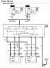
Anyone have any clue on wiring these things? Pinouts or any sort of explanation? Will post results and photos to help anyone going forward, if I can get these wired properly.

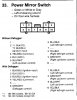
So far I have noticed 4 different switches:
Mine is the 8 wire gray connector with a built in relay (bulge behind retract button)
Grn / Or | Grn / Bl |__________| Y / Blk | Wh / Grn
______ | Grn / Y | R / Blk | Blk | Grn / Wh | ______

I cannot find anyone selling a switch like this at all. No idea what it's even from at this point...

Alps 99-00 EK 9 wire switch (gray connector) built in relay (round bulge behind retract button)
Blk / R | Blk |___________| ______ | Y / R
Grn / Y | Grn / R | Bl / Wh | Grn / Wh | Bl / Blk | Blk / Y

96-98 EK 8 wire switch (white connector) with separate relay
_____ | Blk / Y |______________| Y / R | BLK
Bl / Wh | Bl / Blk | ____ | Y /Blk | Grn / Wh | Bl / Y

-to relay-

(Blue 5 pin connector)
Grn / Y | Wh / Bl | Bl / Y | Blk | Grn / R

Switch with green connector with separate relay (Same as above) - not sure it's model origin
Blk / Y | _____ | Y / Blk | Bl / Blk | Y / R | Grn / Wh | Blk / Wh | ____ | Blk / R | Blk

No idea what switch I have. Not sure if there's an OEM relay somewhere under the dash I haven't found yet. I'm pretty sure the switch I got with the mirrors is not the same switch though. I could be wrong, this is a huge possibility...

Looking into the switches, it seems the Type R and RHD models have the "RETRACT" button on the right side of the selector, and the LHD models have the folding mirror button on the left side (same as mine)
 

RonJ

Banned
Is the center part in your picture the rear side of the dash switch that came with the mirrors?

Have you searched for the circuit diagram for the new mirrors? If you have one, post it.

What car are you installing the mirrors into? Do the current mirrors have or lack the defogger switch?

By the way, there's no relay in stock 96-00 Civic power mirrors.


Wreckless Hype

¯\_(ツ)_/¯
Registered VIP
5+ Year Member
Is the center part in your picture the rear side of the dash switch that came with the mirrors?
Yes, the 10 pin plug with 8 wires is the switch with folding option and built in relay that was provided with my mirrors.

My switch looks exactly like this one (ignore the plug). A lot of other switch I have seen have the "RETRACT" button on the opposite side of the mirror selector switch.

Have you searched for the circuit diagram for the new mirrors? If you have one, post it.
Yea, searched for a bunch. Ended up on Accord, Prelude, EP3, EK9 sites all posting the same thing. Everyone seems to post a 4 piece system with the separate relay but maybe I'm not able to process the setup without the relay? Basically, here's what I got:

For an EG and uses the separate relay, with defogger option:


99-00 Switch with relay, in Spanish (can make out left right, depress and release)


I have another diagram or two, but I guess I saved them on my work PC instead of my thumbdrive. I'll post them up when I get in. Was trying maybe to take what I can from each to figure it out.

What car are you installing the mirrors into? Do the current mirrors have or lack the defogger switch?

By the way, there's no relay in stock 96-00 Civic power mirrors.
Going into my 2000 EX Coupe. I asked to try and make sure I was getting what I needed before I bought them. They have S03 written on them, so they'll fit the doors (I've had them mocked up). I know what I was told they were from, but now looking up the only identification I could find on them, it looks pulls up mirrors for DC and BB chassis as well.


I currently do not have the deffoger option in my car. The new switch also lacks it.

Also, I know the OEM mirrors on my car don't have a relay, but I guess some sort of connecting point? Like a plug or something under the dash? Or do all of the wires go straight from the switch plug to the mirror plugs?

Everyone and their mother has done this swap and puts up a DIY and hand draws diagrams with crayons and MS Paint like a kindergartner, but no one seemingly has ever done it with this combination switch (switch and relay)
 

RonJ

Banned
If I just plug in the new mirror with the OEM plug, the controls are fine, no issues. Obviously when I plug in this switch with the new mirror, it's all mixed up.
Can you elaborate?

By OEM plug, do you mean OEM switch?

By "controls are fine", do you mean up-down and right-left? I wouldn't think that the folding option would work.

it's all mixed up
What exactly happened?

Finally, why do you think that the new switch contains an internal relay?

Also, I know the OEM mirrors on my car don't have a relay, but I guess some sort of connecting point? Like a plug or something under the dash?
I don't follow. What do you mean by connecting point/plug and why are you looking for one?

Or do all of the wires go straight from the switch plug to the mirror plugs?
Below is the detailed circuit diagram for your OEM power mirrors. It comes from pg 141 of the 96-00 Civic Electrical Troubleshooting section of the service manual. It shows ALL connectors in the power mirror circuit.


Also shown below is the OEM switch pin out.


Attachments

Last edited by a moderator:

Wreckless Hype

¯\_(ツ)_/¯
Registered VIP
5+ Year Member
Can you elaborate?

By OEM plug, do you mean OEM switch?

By "controls are fine", do you mean up-down and right-left? I wouldn't think that the folding option would work.
I took off my door panel to remove the tweeter, loosen the mirrors and was going to install my OEM wind deflectors and wanted to look at the mirror wiring to devise a plan of attack. Since it was 3 nuts and a plug, I decided to just mock up the mirrors. I had not touched anything yet in the way of wires or switches, I just unplugged the 3 wire connector from my stock OEM mirror and plugged it into the PFM. The Up / Down / Left / Right all worked.

At this point, the PFM switch was not installed, this is just the stock power mirror control switch that came in the car and only the driver side PFM.


What exactly happened?
I didn't want to mess around with the new switch since from what I read, it's possible to blow the relay if it's wired wrong. I plugged in my PFM switch while the driver's side PFM was installed (The OEM connectors both just plug in without issue, mirror and control switch). I tried to see if I was lucky enough that the motor control wires were in the same place on the PFM switch as the OEM power mirror switch. They were not. I selected left mirror, which worked. Using the direction buttons, the Up/Down did nothing, but the Left/Right moved the mirror up and down. I did not try the folding option because obviously the switch wiring is wrong so I didn't want to chance possibly blowing a relay.

Finally, why do you think that the new switch contains an internal relay?
I don't know for sure, I cannot find anything official by Honda or a relevant part number. I've got an ALPS Korea switch with this fancy nub on the back, behind the fold button. Every single thing I can find describing this switch, says it needs no extra relay module. There was apparently an ALPS Japan switch that looked similar, but required the 5 pin relay module. Nothing, however, I could find published officially by Honda in any way. Otherwise, I'd probably have found what I needed by now.

I don't follow. What do you mean by connecting point/plug and why are you looking for one?
Basically your diagrams show that everything feeds directly off the switch the power and the ground. What I meant was, there is a Y/R for each side. I'm sure Honda didn't just take the 3 Y/R and twist them together and tape them under the dash somewhere. I thought there was a midpoint somewhere that I could trace the wires easier and find out what is going where. Diagrams pretty much remove any need to do that.


Below is the detailed circuit diagram for your OEM power mirrors. It comes from pg 141 of the 96-00 Civic Electrical Troubleshooting section of the service manual. It shows ALL connectors in the power mirror circuit.

Also shown below is the OEM switch pin out.
This was posted before I explained what happened with the PFM switch and PFM on the driver's side. Since the PFM switch seems to have a different pin out for the motor controls, I don't know that these diagrams will really apply to the conversion setup.
 
Last edited by a moderator:

RonJ

Banned
Basically your diagrams show that everything feeds directly off the switch the power and the ground. What I meant was, there is a Y/R for each side. I'm sure Honda didn't just take the 3 Y/R and twist them together and tape them under the dash somewhere. I thought there was a midpoint somewhere that I could trace the wires easier and find out what is going where. Diagrams pretty much remove any need to do that.
I don't follow what your point is possibly because I don't know what Y/R is.

This was posted before I explained what happened with the PFM switch and PFM on the driver's side. Since the PFM switch seems to have a different pin out for the motor controls, I don't know that these diagrams will really apply to the conversion setup.
You must know the OEM circuit and the OEM switch pin out because part of the PFM installation obviously involves re-pinning the OEM connector that will plug into the PFM switch. Your preliminary function test with the PFM switch and PFM mirror has already provided useful information about the PFM switch pin out, if you have the ability to play Sherlock Holmes.

In other words, figuring out the PFM switch pin out by yourself is child's play if you have a multimeter and know how to do a continuity test.

99-00 Switch with relay
And at this point, I'm not convinced that the PFM switch contains a relay. The back nub might just be the extra retract component. For example, note that the EG circuit diagram shows an external folding relay whereas the 99-00 circuit diagram shows no relay whatsoever, either internal or external.
 

Wreckless Hype

¯\_(ツ)_/¯
Registered VIP
5+ Year Member
I don't follow what your point is possibly because I don't know what Y/R is.
Yellow/Red wire, sorry. I think at this point, with the diagrams and pinouts provided directly from the service manual, you've ousted my need to locate this phantom connection that doesn't exist. Essentially I don't need to expel any more energy there.

You must know the OEM circuit and the OEM switch pin out because part of the PFM installation obviously involves re-pinning the OEM connector that will plug into the PFM switch. Your preliminary function test with the PFM switch and PFM mirror has already provided useful information about the PFM switch pin out, if you have the ability to play Sherlock Holmes.
I agree the OEM pinout / circuit info is very important. I'll need to note all of the original harness wires and the new harness wires and try to figure out what goes where. I was pretty much hoping someone had some insight on this already but this conversion with this type of switch doesn't seem very common..

If I can find the power on the switch, and I can ground the black wire, I should be able to just connect to each wire and the ground and play with the switch controls to find out where I'm getting power when I hit whatever I hit? I've literally never done this before but am more than willing to dive into it.

Dammit, we type too fast and ninja edit

And at this point, I'm not convinced that the PFM switch contains a relay. The back nub might just be the extra retract component. For example, note that the EG circuit diagram shows an external folding relay whereas the 99-00 circuit diagram shows no relay whatsoever, either internal or external.
I can't disagree, I have nothing to stand on, just what I've read. And I live by a famous quote, "The problem with internet quotes is that you cant always depend on their accuracy" -Abraham Lincoln. So I can for now act like it may have a relay while I get the other controls figured out, then I should be able to narrow down what wires control the folding option and if it's not working, I'll need the relay for it. Obviously the power to the motors works and the controls work without relays, even though they're a little mixed up.
 

RonJ

Banned
See text edits in my last post.

After studying the EG PFM circuit, the relay appears to exist to allow the mirrors to be folded when the key is off.

The 99-00 PFM circuit shows that this "key off" function and the PFM relay was eventually eliminated, so the mirrors only work with the key in ON(II).

Let me try to sum up for you what this conversion probably entails:

1) Do continuity tests on the PFM switch to determine its exact pin out and how it differs from the OEM switch.

2) Repin the OEM switch connector (wire harness side) to match the PFM switch. Do you know how to repin a connector?

3) No OEM wires exist for the retract function, so you need to add these two wires to the OEM switch connector (wire harness side) and run them to the mirror connectors in the driver and passenger doors.

4) Enjoy PFMs.
 

Wreckless Hype

¯\_(ツ)_/¯
Registered VIP
5+ Year Member
1) Do continuity tests on the PFM switch to determine its exact pin out and how it differs from the OEM switch.

2) Repin the OEM switch connector (wire harness side) to match the PFM switch. Do you know how to repin a connector?

3) No OEM wires exist for the retract function, so you need to add these two wires to the OEM switch connector (wire harness side) and run them to the mirror connectors in the driver and passenger doors.

4) Enjoy PFMs.
I know basic continuity testing, finding cables, etc. This is going to be a little different for me and something new, so we'll see. Would I be correct assuming checking continuity is checking each pin against power or the ground while hitting different controls on the switch, unplugged from any power? Apologies, so many wiring diagrams and pinouts the past couple days, my head is spinning.

Repinning the connector won't be an issue. I should be able to pop out a couple pins on the PFM switch pigtail so I can push them into my OEM connector and solder new wires on for the folding operation.
 

RonJ

Banned
If I can find the power on the switch, and I can ground the black wire, I should be able to just connect to each wire and the ground and play with the switch controls to find out where I'm getting power when I hit whatever I hit? I've literally never done this before but am more than willing to dive into it.

I can't disagree, I have nothing to stand on, just what I've read. And I live by a famous quote, "The problem with internet quotes is that you cant always depend on their accuracy" -Abraham Lincoln. So I can for now act like it may have a relay while I get the other controls figured out, then I should be able to narrow down what wires control the folding option and if it's not working, I'll need the relay for it. Obviously the power to the motors works and the controls work without relays, even though they're a little mixed up.
It's important for me to reiterate that this job will not involve any cutting/splicing of any OEM wires. All that will be needed is to repin a few wires in the OEM connector that plugs into the PFM switch.

The vast majority of the work will be running the two "retract" wires from the switch connector to the mirror connectors in the two doors.

I find that you are a very intelligent person, but you are a bit overly inclined to make potentially incorrect assumptions.

And with a small effort, you can learn how to read a simple circuit diagram. With such knowledge, you would see that the 99-00 PFM circuit has no relays and also understand the function of the relay in the EG PFM circuit.

Good luck with the conversion. Post a video when you have them working.
 

Wreckless Hype

¯\_(ツ)_/¯
Registered VIP
5+ Year Member
It's important for me to reiterate that this job will not involve any cutting/splicing of any OEM wires. All that will be needed is to repin a few wires in the OEM connector that plugs into the PFM switch.
I don't like cutting s**t if I don't have to. My thought was:
Pull the OEM switch
Depin the OEM connector
Pull 2 pins from PFM pigtail provided with my conversion
Repin OEM connector to work with PFM switch
ADD 2 pins from provided pigtail as the "Retract" wires

The vast majority of the work will be running the two "retract" wires from the switch connector to the mirror connectors in the two doors.
For me, half of the job will be learning how to come up with my own pin out. The hard part after will be running the two wires through the door and not ripping apart the rubber seals between the doors and chassis.

I find that you are a very intelligent person, but you are a bit overly inclined to make potentially incorrect assumptions.
So sweet. And yea, I can see what you mean, but that's also why I ask questions and try to get specifics. I think I'm getting better :lol:

And with a small effort, you can learn how to read a simple circuit diagram. With such knowledge, you would see that the 99-00 PFM circuit has no relays and also understand the function of the relay in the EG PFM circuit.

Good luck with the conversion. Post a video when you have them working.
Working on not shutting out what I don't know. But you can't just look at something and then know what it is. I'm sure when I actually do the testing with my multimeter, the diagrams should make a little more sense.

I'll give it a shot and will keep updating this thread with progress, pinouts, photos, video, whatever.
 

RonJ

Banned
Would I be correct assuming checking continuity is checking each pin against power or the ground while hitting different controls on the switch, unplugged from any power?
The tests initially do not involve any voltage measurements. Tests will be done on the unplugged PFM switch using the continuity setting on your multimeter.

Ask me any specific question.

I plugged in my PFM switch while the driver's side PFM was installed (The OEM connectors both just plug in without issue, mirror and control switch)...I selected left mirror, which worked. Using the direction buttons, the Up/Down did nothing, but the Left/Right moved the mirror up and down.
Test time. Based on these^ preliminary tests using the PFM switch, what conclusions are you already able to draw? Sherlock, it's time for you to tease out all information that is currently available to you.

For me, half of the job will be learning how to come up with my own pin out.
I disagree. You only think determining the pin out is half the job because you don't yet understand how to do it. Running the new wires is where the work is.

But you can't just look at something and then know what it is.
Stare at the circuit diagram. Try to logic what you can, and then ask me any specific questions for things that are unclear.
 

Wreckless Hype

¯\_(ツ)_/¯
Registered VIP
5+ Year Member
The tests initially do not involve any voltage measurements. Tests will be done on the unplugged PFM switch using the continuity setting on your multimeter.
Picked up on that towards the end here, heh.

Test time. Based on these^ preliminary tests using the PFM switch, what conclusions are you already able to draw? Sherlock, it's time for you to tease out all information that is currently available to you.
I've got power to the mirror, pin 2 can be left as is.
If there's a wire on the Left side Up/Down pin, it's going to the wrong lead on the mirror end.
The Left side, Left/Right on the OEM switch is pin 6, but on the PFM, pin 5 powers the motor up and down when I hit the Left/Right button.

I disagree. You only think determining the pin out is half the job because you don't yet understand how to do it. Running the new wires is where the work is.
Preliminary judgement I suppose, on account of I have no idea what I'm doing yet. But I'm sure I'll get the hang of it.

Stare at the circuit diagram. Try to logic what you can, and then ask me any specific questions for things that are unclear.
:thumbs up
 

RonJ

Banned
I've got power to the mirror, pin 2 can be left as is.
Perfect.

All electrical circuits have both power and ground. Can you make any conclusion about the ground wire position in the OEM switch connector?

If there's a wire on the Left side Up/Down pin, it's going to the wrong lead on the mirror end.
The Left side, Left/Right on the OEM switch is pin 6, but on the PFM, pin 5 powers the motor up and down when I hit the Left/Right button.
You are on the right track here, but first more details about your preliminary test results are needed. When you pressed left, did the mirror move up or down? Likewise, when you pressed right, did the mirror move up or down?
 

RonJ

Banned
Also, your PFM switch came with a connector with cut wires attached.

Did the PFM mirrors also have connectors with cut wires plugged into them? If so, post pictures.
 

Wreckless Hype

¯\_(ツ)_/¯
Registered VIP
5+ Year Member
Perfect.

All electrical circuits have both power and ground. Can you make any conclusion about the ground wire position in the OEM switch connector?
Yea, whoops. Leave pin 4 alone also.

You are on the right track here, but first more details about your preliminary test results are needed. When you pressed left, did the mirror move up or down? Likewise, when you pressed right, did the mirror move up or down?
Crap. It's kind of a blur at this point, but I believe it was left = up, right = down. I'm sort of confused by the specifics here. I guess I thought if the Left / Right action was sending the current through the wire to the wrong pin, in this case the Up / Down motor, I figured it was just a wire that had to be moved. Then I'm curious where this is leading.

Pin 3 is my common and pin 5 is moving my mirror, since that's where the wires are landed in the harness. If these are backwards on the PFM switch, would then the movement be backwards (Up / Down = Down / Up) when it's corrected?

Edit: So if them moving this way with the wires crossed is a correct notion where Left Up and Right Down shows proper motor signal, then 3 should be my common and should not be moved.
 

Wreckless Hype

¯\_(ツ)_/¯
Registered VIP
5+ Year Member
Also, your PFM switch came with the connector with cut wires attached.

Did the mirrors also have connectors with cut wires plugged into them? If so, post pictures.
The image I posted in the original post is what I have waiting to go in. Everything came with pig tails attached thankfully, so I can easily depin them and add the extra pins to my current setup and solder wire in to complete the circuits.

Edit: The Green/Yellow and Blue/Red are alternated on the mirror plugs. I think I read in a couple threads that this is to make sure both sides close and open together. So the #1 pin (Looking at the connector from the wired side, tab up) would be a motion to move the mirror arms one way and the pin below it would move the mirror arms the other way. So if they're alternated, the arms would move opposite each other allowing drive side to move in (CCW) and passenger side to move in (CW)

I'm not sure what the Yellow/White is going to be for yet, I need to look at my OEM mirror plugs again and see what the positions of the wires are. I believe the middle two wires on the top of the plugs are for the Up / Down and Left / Right motors. (Yellow / Black & Yellow / Red)(Blue White & Blue / Black)
 

RonJ

Banned
Yea, whoops. Leave pin 4 alone also.
Perfect again. So you already know that 2 wire pins are where they should be. I think the PFM switch may require 9 total wires (not 8), so 7 pins to go. The field is now a bit smaller.

Also, do you already know whether the pinouts for the PFM and OEM connectors at the mirrors are identical or different? Furthermore, are the wire color pinouts of the PFM and OEM mirror connectors identical or different? Do the wire colors in the PFM mirror connectors match those in the PFM switch connector?

I believe it was left = up, right = down. I'm sort of confused by the specifics here. I guess I thought if the Left / Right action was sending the current through the wire to the wrong pin, in this case the Up / Down motor, I figured it was just a wire that had to be moved. Then I'm curious where this is leading
You are basically correct; however, I'm not sure that you are aware that up-down and right-left are simply determined by current polarity in the circuit.

Look at the OEM circuit diagram I posted. With the switch toggled to control the left mirror, OEM switch connector pins 3 and 6 control left and right movement, whereas OEM switch pins 3 and 5 control up and down movement. When you press left-right in the PFM switch, you are controlling pins 3 and 5. However, you don't know whether pins 3 and 5 are reversed in the PFM switch. Knowing whether left = up versus down will help sort this out.

Why do you think that the up-down does not work at all in the PFM switch? What might this be telling you?
 

Wreckless Hype

¯\_(ツ)_/¯
Registered VIP
5+ Year Member
Perfect again. So you already know that 2 wire pins are where they should be. I think the PFM switch may require 9 total wires (not 8), so 7 pins to go. The field is now a bit smaller.
Yes.

Also, do you already know whether the pinouts for the PFM and OEM connectors at the mirrors are identical or different?
If I was able to use my OEM PM switch with the PFM connected and all directions worked, then that SHOULD tell me that the pinouts for the common and the 2 wires for the Horiz / Vert movement is correct.

Furthermore, are the wire color pinouts of the PFM and OEM mirror connectors identical or different? Do the wire colors in the PFM mirror connectors match those in the PFM switch connector?
None of the colors match, that was part of my confusion. Also the PFM switch has almost none of the same color wires as the PFM themselves so that's why I was curious how they all connected.


You are basically correct; however, I'm not sure that you are aware that up-down and right-left are simply determined by current polarity in the circuit.

Look at the OEM circuit diagram I posted. With the switch toggled to control the left mirror, OEM switch connector pins 3 and 6 control left and right movement, whereas OEM switch pins 3 and 5 control up and down movement. When you press left-right in the PFM switch, you are controlling pins 3 and 5. However, you don't know whether pins 3 and 5 are reversed in the PFM switch. Knowing whether left = up versus down will help sort this out.
That's pretty much what I was guessing. So I need to know which direction which polarity.

Looking at the bottom of the diagram at the Left mirror, following up the Yellow/Red to the Up / Down and Left / Right movements, it looks like Down and Left share the same circuit and Up and Right share another. So if I hit Left for the Left mirror and it moves Up, my polarity is reversed.

Why do you think that the up-down does not work at all in the PFM switch? What might this be telling?
If my polarity is reversed for the Left / Right switch motion (hitting the common instead of the motor movement circuit and vice versa), then possibly the button trying to use the L/R and U/D wires instead of hitting the common at all Common with the U/D (if it were switched properly)
 

RonJ

Banned
If I was able to use my OEM PM switch with the PFM connected and all directions worked, then that SHOULD tell me that the pinouts for the common and the 2 wires for the Horiz / Vert movement is correct.
Correct. Aside from the folding function, the PFM and OEM mirrors are identical circuit- and pinout- wise. By process of elimination, the two extra wires in the PFM mirror connector control the folding function. Again, fold-in versus fold-out are controlled by the polarity of the current. How could you easily determine which polarity controls which direction?

None of the colors match, that was part of my confusion. Also the PFM switch has almost none of the same color wires as the PFM themselves so that's why I was curious how they all connected.
You received mix and match parts.

Looking at the bottom of the diagram at the Left mirror, following up the Yellow/Red to the Up / Down and Left / Right movements, it looks like Down and Left share the same circuit and Up and Right share another. So if I hit Left for the Left mirror and it moves Up, my polarity is reversed.
Correct, assuming that the circuitry of the OEM and PFM switches isn't reversed. This is where the continuity tests on the switch will become invaluable. Of course, you first need to verify that left = up.

If my polarity is reversed for the Left / Right switch motion (hitting the common instead of the motor movement circuit and vice versa), then possibly the button trying to use the L/R and U/D wires instead of hitting the common at all Common with the U/D (if it were switched properly)
Correct. So do you think that pins 3 and 5 are reversed or matched in the OEM and PFM switches?


Top