Shifter Stuck in Park, 5th Gen Civic

Cojoe15

New Member
Hello,

Car: 1993 Honda Civic DX 1.5L Automatic Sedan

I have a problem with my shifter being stuck in park. Before you respond please read entire post.

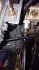
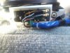
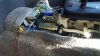
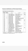
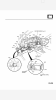
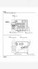
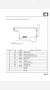
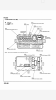
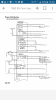
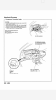
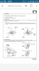
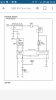
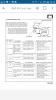
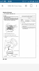
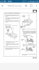
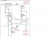
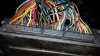
In November of 2015 I had my ECU go out on me and I took it to the dealership to get replaced. This spring (2016) I bought new struts to replace on all four tires. Getting into that I nearly replaced all the suspension except the front lower control arms. Everything else suspension is brand new on my car. Before doing this work one day my shift lever wouldn't go into park so I just stuck a small pocket screw driver into the release lock. I thought it was the safety neutral switch so I replaced that while my car sat thinking that was the problem. While the car was parked for three months I worked on the suspension I never got to try the safety neutral switch. Got the suspension done and went to take it for an alignment and it was still stuck in park. I looked on here and a lot of people suggested the brake switch that controls your brake lights. I do have brake lights so I didn't think that was the problem. I did take the connector out and shorted the wires together. My brake lights came on but the shifter was still stuck in park. I got onto a Honda parts site and started looking at diagrams and seen that there is a shifter solenoid that releases the shift lock. Today I went to the local junk yard and got a shift solenoid off of a 1994 Honda Civic DX. Came home to try it out. While I had the cover off of the gear shifter I put the key in and right before the engine cranks over, during the same time you hear the fuel pump prime the shift solenoid primed or jumped a bit. Kind of like it tested itself. That was the old one. I put the one on from the junk yard and it did the same thing. I even started the car to see if that what it needed. Still the gear shifter is stuck in park. I found the 92-95 Honda Civic service manual and looked up the diagrams and wiring for the shifter. I found out that there is an interlock control unit next to the brake pedal. One of the yellow wires from the shift solenoid comes from that and the other comes from fuse 15 (10amp) and a fuse 42 that I couldn't find that should be under the hood next to the battery according to the service manual. I replaced fuse 15 for the heck of it and even went to the junk yard and got the interlock control unit. The junk yard interlock control unit did not do anything still the same problem. So far I've replaced or tested, safety neutral switch, shift solenoid, control interlock unit, fuse 15, brake light switch and I even check the connectors between all areas. It could be that one of the junk yard parts isn't working. I don't have a meter on me to check voltages. I just know that it isn't working. I'm attaching pictures of the the units that I'm talking about and even screen shots of the parts in the manual. I'm missing something. Could the brake light switch be my problem even though I shorted the wire out? This shouldn't be that difficult especially with the service manual pages. Please look over everything for me and give me some suggestions. I even looked at my bulbs and had one out on me. Replaced that bulb and still having this problem. Look at reply for other screenshots.


break light switch 93 Honda Civic.jpeg safety neutral switch 93 Honda Civic.jpeg
shift solenoid 93 Honda Civic.jpeg
23-24.png
23-25.png
23-46.png
23-47.png
23-48.png
23-52.png
23-148.png
 

Cojoe15

New Member
I'll head to Harbor Freight tomorrow and pick one up. I'll post results on all test points tomorrow evening.
 

Cojoe15

New Member
I'm going to borrow a meter from work and test the system. Would anyone know what are the voltages going to the interlock control unit. I found the break over voltage for the shift solenoid at 6-6.3v. So I should be seeing that voltage when I press the brake pedal. I'll post results tonight. I posted a youtube video to show. I would like to test the interlock while I'm at work with these fancy machines.


Cojoe15

New Member
Okay so here are my results of everything.

Battery Voltage without the car running. = 12.5v
Battery Voltage of the car running. = 14.43v
Voltage of fuse 42. 14.44v
Shift lock solenoid without brake pedal depressed. 0.25v
Shift lock solenoid with brake pedal depressed. .051v
Brake light switch white/green wire to ground. 14.32v
Brake light switch green/white wire to ground 0v. Brake peddle depressed goes to 12.9v. So we know the brake light switch is working correctly.
Shift solenoid jumps to 1.8v when Civic starts up goes down and stays at 0.21v while vehicle is started and while pressing brake peddle. I should be getting 6v when brake peddle is depressed to activate shift lock solenoid.
Fuse 15 voltage 14.2v

On to page 23-151 I will go by the shift number 1-4. I didn't test the key interlock system. I took the steering wheel apart and I couldn't find that key interlock solenoid.
1.) 14.14v
2a.) ignition switch on with compressed brake pedal. 13.7 constant. This should be less than 1v.
2b.) ignition switch on with compressed brake pedal and accelerator. 11.97v. That is not 3v.
So this means that the PGM-FI ECU(ECU was replaced in December of 2015 by Honda) or open wire or faulty brake switch (which we know this is good) or faulty throttle positioning sensor. I did end up testing the throttle positioning sensor by putting meter ground to battery and positive lead to red/white wire. I watch voltage drop smoothly through 4.6v down to .5v. I don't think that is bad. This is either means that Honda put in a crappy ECU or I have an open wire in the system. I highly doubt I have an open wire someone. Nothing has been done to the car to prove that.
3.) shift lever in position P. I got 11.93 ohms.
4.)12.4v

What do you guys think I should do? Take the car back to Honda and show them what I found that it's pointing to their ECU or something else? I just found the receipt and it was done on November 24, 2015. I'm assuming I have a one year warranty on this. I paid $511.34 for this. ECU cost $150 and labor was 329. Isn't the ECU right on the passenger floor board. Remove the carpet piece and it's right there. I wonder why they charged so much in labor. If I got to the dealership we all know I'm paying at least $100 just for them to look at the car. I can still drive the car and it runs perfectly. It's just annoying using a key or keeping a screw driver shoved in the shift release hole.
 

Cojoe15

New Member
Start by focusing on the shift solenoid readings, which are clearly problematic.

Were the tests result below obtained on the Yel wire in the unplugged shift solenoid connector with the engine running?

I did post results for 3 and 4. 3.)


Do the speedometer, tach, and gauges work in the cluster?


No. The solenoid should receive battery voltage (12.5V with engine off/key on or 14.4V with engine running).


Also post results for tests 3 and 4.
Start by focusing on the shift solenoid readings, which are clearly problematic.

Were the tests result below obtained on the Yel wire in the unplugged shift solenoid connector with the engine running?


Do the speedometer, tach, and gauges work in the cluster?


No. The solenoid should receive battery voltage (12.5V with engine off/key on or 14.4V with engine running).


Continuity test the Wht/Red wire between ICU connector and the ECU connector. It may be broken.
Start by focusing on the shift solenoid readings, which are clearly problematic.

Were the test results below obtained on the Yel wire in the unplugged shift solenoid connector with the engine running?


Do the speedometer, tach, and gauges work in the cluster?


No. The solenoid should receive battery voltage (12.5V with engine off/key on or 14.4V with engine running).


Continuity test the Wht/Red wire between ICU connector and the ECU connector. It may be broken.
It's highly unlikely that they are broken but could be. I tested the yellow/black as ground and the yellow as positive and that's what I got. I'll go out and check them as both positive. They were tested unplugged and while the car was running. Yes everything else does work. I did today swap my instrument cluster with one that had a tachometer in it but it all is working good. The shifter is the onlyy thing im having problems with. To me the interlock control unit is not getting what it needs. I believe the solid yellow wire goes to fuse 15 or 42 while the yellow black wire plugs into the interlock control unit.
 

Cojoe15

New Member
Your solenoid test results are inconsistent with your ICU test results. In the unplugged solenoid connector, you should measure battery voltage at the Yel wire with the shifter in park and the key in ON(II). In contrast, you should measure less than a volt or no voltage at the Yel/Blk wire under the same conditions.


Just follow the troubleshooting and go where it takes you.


The problem you have found so far at the ICU connector is the unexpectedly high voltage readings at the Wht/Red wire.

1) If you neither press the brake nor accelerator, what voltage do you measure at the Wht/Red wire with the key in ON(II)?

2) If you unplug ECU connector D, does the voltage drop to ~0V at the Wht/Red wire in the ICU connector?

I'll have to check on that ECU connector D if the voltage drops but here I found some interesting voltages. As we saw with the video that I made earlier that the break over voltage for the shift lock solenoid was at least 6 volts. That what I was referring to. I did this a couple of different ways and I hope this helps. I will have to check to see if I'm getting the same voltages to the yellow/black wire going into the ICU. I wanted to post these first.

Key in ON position (Unplugged from shift solenoid) NOT pressing brake pedal while testing.
  • Yellow/Black to ground = 0v.
  • Yellow to ground = 12.289v. (Battery voltage)
While car is running (Unplugged from shift solenoid) HELD in brake pedal
  • Yellow/Black to ground = 0v
  • Yellow to ground = 14.02v (Battery voltage)
No voltage came from Yellow/Black while connector was unplugged from shift solenoid.


Key in ON position plugged into shift solenoid. (NOT pressing brake pedal)
  • Yellow/Black to ground = 12.489v (Battery voltage)
  • Yellow to ground = 12.489v (Battery voltage)
Car running plugged into shift solenoid.
  • Yellow/Black to ground = 13.97v
  • Yellow to ground = 14.03v
Even pressed the brake pedal with no change in voltage. To me with the connector being plugged into the shift solenoid and it getting over that 6v that takes for it to work you think instead of the shifter being stuck in the P position that the shifter would never get stuck being that the solenoid was in an open position all the time. The shifter does move right when the key goes into the ON position right before the car cranks over but after that it doesn't work. I'm going to go back outside and measure the voltages of the 7 wires going into the ICU and do some ohm testing also. I post what I find.
 

Cojoe15

New Member
These diagrams may be informative to you in later tests:

View attachment 28450


View attachment 28451
Yes that is what I'm saying. I know the solenoid works because I tested it at work on a power supply. When it worked the voltage was at 6v. That means anything over 6v will trigger the shift solenoid to work. I already replaced the shift position control switch aka safety neutral switch.

These voltages I tested from the connector going into the ICU with the car in the ON position and the car running. Also checked the ohms (resistance of the wires too.) Everything is tested to ground.

Car in ON position unplugged from ICU. Ohm reading tested nothing if not posted.
  1. Yellow = 12.248v (Battery voltage)
  2. Yellow/Black = 12.253v
  3. Green/White = 0v
  4. White/Red = 0v
  5. White/Blue = 0v
  6. White/Yellow 0v
  7. Black = 0v; 4.5ohms
Car running unplugged from ICU all tested to ground. Ohm reading tested nothing if not posted.
  1. Yellow = 13.9v
  2. Yellow/Black = 13.89v
  3. Green/White = 0.0162v; 27ohms
  4. White/Red = 0.5394v (this passes the test on page 23-151 but fails when plugged into ICU)
  5. White/Blue = 0.0097v
  6. White/Yellow = 0.0010v
  7. Black = 0v; 7ohms
I'll go out and test these below like you asked.

1) If you neither press the brake nor accelerator, what voltage do you measure at the Wht/Red wire with the key in ON(II)?

2) If you unplug ECU connector D, does the voltage drop to ~0V at the Wht/Red wire in the ICU connector?


I do have an ICU and another shift lock solenoid that I got from the junk yard. I put both of them in and nothing changed.
 

Cojoe15

New Member
Hey BooFoo I do apprechaite you trying to help me out. Reading question one I answered above in the voltage readings. I'm going to have to find connector D that plugs into the ECU and let you know what happens with the voltage.
 

Cojoe15

New Member
Yes, but to ensure the new reading is reproducible, please repeat the Wht/Red wire voltage test with ICU connector unplugged and key in ON(II) under these three conditions:

1) No pedal pressed
2) Brake pressed
3) Brake + accel pressed


ECU connectors:

http://www.phearable.net/images/tech/wiring/obd1.pin.schematics.gif
Thanks for the website. I now know what to look for. With that should I just unplug it and look at the voltages without running the car. Just be in the ON position?

Here are the voltages for White/Red wire.

On Position Unplugged from ICU
  1. No Pedal Pressed = 0.35v
  2. Brake Pedal Pressed = 0.35v
  3. Brake and Accelerator Pressed = 0.35v
Car running unplugged from ICU
  1. No Pedal Pressed = 0.5283v
  2. Brake Pressed = 0.53v
  3. Brake and Accelerator Pressed = 0.53v
All those still pass the test but I did two more tests.

On Position Plugged into ICU
  1. No Pedal Pressed = 12.2v
  2. Brake Pedal Pressed = 11.9v
  3. Brake and Accelerator Pressed = 11.9v
Running Plugged into ICU
  1. No Pedal = 13.67v
  2. Brake Pressed = 13.67v
  3. Brake and Accelerator Pressed = 13.6v
So while it's plugged into the ICU it's getting battery voltage at all times when it's supposed to be under 1v.
 

Cojoe15

New Member
Test 2 passes but test 3 fails in these important tests. I presume that test 1 should be 3V or higher, though this is not specified in the service manual.

It's possible that the Wht/Red wire is broken.

Does voltage change at the Wht/Red wire with ECU connector D unplugged?
I haven't gotten to disconnecting connector D yet. I'm sitting here looking over all the voltages. With page 23-151 it talks about exactly what is happening to me. It the NOTE section says go to 23-161. The only white/red wire on their goes from Number 36 (50amp) to Number 3 (7.5amp) fuses and that goes into the integrated control unit.

I'm rewriting this because I think this has something to do with it too. Thinking out loud here.

These are tests according to page 23-151.

Yellow = 12.36 pass
White/Red
  1. Ignition switch on stepping on brake pedal. .345v pass
  2. Ignitions switch on step on brake and accel pedal. .35v FAIL
Green/White = 15.32ohms pass
Yellow/Black = 12.314v pass
Black = 1.01ohms pass
Green/White = 16ohm pass
White/Yellow = 0v FAIL
White/Blue = 0v FAIL

All tested according to how page 23-151 wants you to test it. Unplugged and according to test conditions. Since White/Yellow and White/Blue have key interlock solenoid being a suspect I wonder if I should try to find that and test it out. Tomorrow I'm going to test removing plug D from ECU and try to find this Key Interlock Solenoid and test that too. I'll try to find a different location for that White/Red wire and do a ohm test on it to see if it's broken.
 

Cojoe15

New Member
Test 2 passes but test 3 fails in these important tests. I presume that test 1 should be 3V or higher, though this is not specified in the service manual.

It's possible that the Wht/Red wire is broken.

Does voltage change at the Wht/Red wire with ECU connector D unplugged?

How should I test White/Red wire with the plug D unplugged?
  1. Car started, check voltage to ground?
  2. Key in ON position check voltage to ground?
  3. Checked continuity from plug D white/red to white/red on the interlock control unit?
I'm kind of hasintent on unplugging that and testing with it unplugged. Wouldn't that throw a check engine light or cause something else to happen?
 

Cojoe15

New Member
This^ is likely a separate problem. What voltage do you measure at the Wht/Grn wire in the interlock solenoid connector?
White/Green wire coming from the Key Interlock solenoid/Key Interlock Switch? Diagram on page 23-148 and 23-150. The white/green wire goes into the key interlock switch/key interlock solenoid. The white/green wire also powers the horns/brake lights. Since those work I'm not faulting the white/green wire unless that section could have a break in it. I'll check continuity between the white/green wire going into the brake light switch to the white/green wire going into the key interlock switch/key interlock solenoid. If that's good that wire is good. White/Blue and White/Yellow comes out of key interlock switch/key interlock solenoid. I wasn't getting those voltages according to the Interlock Control Unit test on page 23-151. If those aren't giving the right voltages the Interlock control unit wont work properly too. I still like the idea of checking the white/red wire since it goes from the interlock control unit straight to the PGM-FI ECU being that's the shift lock circuit inside of the interlock control unit. I could do a diode test between white/yellow to yellow/black, white/yellow to green/white and yellow/black to green/white inside of the interlock control unit. I could have two bad interlock control units. One of these pieces on page 23-150 is bad.


These:
2. Key in ON(II) position check voltage to ground at ICU connector?
3. Key OFF; Checked continuity from plug D white/red to white/red on the interlock control unit?


There's no risk.
I'll test this later tonight.
 
Last edited:

Cojoe15

New Member
Were you having any problems with the key interlock system? Were you unable to remove the key with the shifter not in Park?

The Wht/Blu and Wht/Yel wires get their voltage from the Wht/Grn wire. That's the rationale for testing whether the Wht/Grn wire gets battery voltage.
No I'm not having any problem taking the key out when the car is in park. It's just strange that I'm not getting any voltage coming out of the White/Blue or White/Yellow wires coming from the Key interlock system. I have the battery voltage going into it and then it stops. I'm not sure if those two wires only supply voltage during that time of park and turning the key to pull it out. Everything else seems logical except that key system and the white/red wire getting the .5 when unplugged but getting battery voltage while plugged in.

Thinking out loud again here.

If that white/red wire is directly connected to the ECU by connector D pin 18 with the wire getting .5 volts like it should according to page 23-151 unplugged from the interlock control unit that means that the ECU is putting out the correct voltage. That would mean the white/red coming from the ECU to the interlock was fine. Correct? Then as soon as you plug it into the interlock control unit it jump up to battery voltage. Wouldn't that mean there is a short in the interlock control unit inside the shift lock circuit? Look at page 23-150. The yellow wire goes directly into the interlock control unit into the shift lock circuit. That goes to the white/red wire. That could also be the reason why I'm getting battery voltage along the shift lock solenoid but it's not being activate because it could be getting back feed signals from the interlock control unit. Yellow and Yellow/Black could be shorted together inside that system. I can test that later tonight. I'm going to test all the points going into the interlock control unit according to the diagram on that page.
 

Cojoe15

New Member
But are you unable to remove key when shifter is not in park?


Where did you post this^?


You don't know that the low voltage comes from the ECU until you unplug ECU connector D and retest voltage.


The service manual does not provide predicted outcomes for doing the voltage test with ICU connected, so you don't know how to interpret the result.
I can remove the key with no problem while the car is in the park position. Meaning from what I know with the voltages of the Key interlock switch is working. In post #7 I mentioned that the brake light switch that has the white/green wire going into is battery voltage. The key interlock part of the that unit could work fine but that key interlock solenoid portion could be faulty. I will unplug connector D and see if the ECU is giving out .5 volts or if something on the white/red line is giving that voltage. From what I can tell of all the wiring diagrams that is the only white/red wire there is. I get that the service manual doesn't tell you have to interpret it but you can come up with your on conclusions. I'll check the ECU later tonight and check the Key Interlock Switch/Key Interlock Solenoid between A, B, C. I should have continuity between C and B. With battery voltage coming into A, B and C should have pretty close to that voltage as well when the Key Interlock Solenoid is tripped.
 

Cojoe15

New Member
This is what I'm trying to explain. Something should be coming out of B (White/Blue) and C (White/Yellow) to go into the Interlock Control Unit. A thought of mine is how they want you to test white/red by pressing on the brake to get less that 1v but how or why should it be if I press on the brake and accelerator I should get 3v? That doesn't make sense to me. Where does the accelerator tie into this at? Interlock System Circuit Diagram.jpg
 

Cojoe15

New Member
You know what as I'm reading this over and over again, to test white/blue and white/yellow key has to be in ACC mode. I tested it with the key on the ON(II) mode. Thinking that, the only problem now is the white/red wire coming from the ECU.
 

Cojoe15

New Member
Here are my thoughts. Think of the shift lock portion of the ICU as a relay where ECU voltage output to the Wht/Red wire controls whether battery voltage on the Yel/Blk wire becomes connected to the ground source (G201/G401) provided by the Grn/Wht wire.

When voltage on the Wht/Red wire is less than 1V (brake pedal pressed), the relay is activated to provide ground, thereby allowing the shifter to move out of Park.

When voltage on the Wht/Red wire is 3V or higher (brake+accel pressed or no pedals pressed), the relay is unable to provide ground, thereby preventing the shifter from moving out of Park.

Does this make sense?
Yeah that does make sense. I think the key solenoid is okay since I can take the key out when in park. Makes sense why they asked to press the brake pedal to tell the ECU that it's pressed to drop the voltage on the white/red wire to trip the shift lock solenoid to open. Where as if both brake and accelerator or nothing is pressed being a safety feature so you can't take the shifter out of park. If the ECU ends up being okay then I must have gotten a faulty interlock control unit at the junk yard. I'll post results in about 2 hours.

  1. Voltage of connector D pin 18 to ground with no key =
  2. Voltage of connector D pin 18 to ground with key in ON(II) =
  3. Voltage of connector D pin 18 to ground with engine running =
  4. Continuity from Connector D pin 18 to White/Red on Interlock control unit =
  5. Voltage of pin 18 on ECU to ground of brake pedal pressed with key in ON(II) =
  6. Voltage of pin 18 on ECU to ground of brake pedal pressed with engine running =
  7. Voltage of pin 18 on ECU to ground with brake/accelerator pressed in ON(II)=
  8. Voltage of pin 18 on ECU to ground with brake/accelerator pressed with engine running=
Is that to much or should there be more? The ECU pin 18 should be putting out different voltages depending on it's state.
 

Cojoe15

New Member
I'm not sure at this point whether the ECU outputs voltage or grounds voltage from the ICU Yel wire. I'm leaning toward the latter.

Given the known issue with voltage at the Wht/Red wire, I don't think you need to invoke a bad ICU at this point.

I think these are the key tests. Do them with the ICU connector unplugged.
  1. Voltage of connector D pin 18 to ground with no key =
  2. Voltage of connector D pin 18 to ground with key in ON(II) =
  3. Voltage of connector D pin 18 on ECU to ground of brake pedal pressed with key in ON(II) =
  4. Voltage of connector D pin 18 on ECU to ground with brake/accelerator pressed in ON(II)=
Also do these tests
  1. Voltage at the Wht/Red wire in the unplugged ICU connector with or without ECU connector D connector unplugged and key in ON(II) =
  2. Unplug ICU and ECU D connectors and turn key off: Continuity from Connector D pin 18 to White/Red on Interlock control unit =
These results surprised me. I took a picture of the ECU. Connector D pin 18 is a red/green wire.

ICU connector unplugged with connector D still plugged into ECU.
  1. Voltage of connector D pin 18 to ground with no key = 0v
  2. Voltage of connector D pin 18 to ground in ON (II) = 11.49v
  3. Voltage of connector D pin 18 on ECU to ground with brake pedal pressed in ON(II).= 11.2v
  4. Voltage of connector D pin 18 on ECU to ground with brake+accelerator pressed in ON(II) = 11.2v
  1. Voltage of the white/red unplugged from ICU with connector D plugged into the ECU in ON(II) = .35v
  2. Voltage of the white/red unplugged from ICU with connector D unplugged from ECU in ON(II) = 3.6v
  3. Continuity check between unplugged ICU connector (white/red wire) and unplugged connector D pin 18 with the key out. NOT CONNECTED
Where do the white/red and red/green wire meet at? It is interesting that according to page 23-151 I'm getting the voltages of .35v and 3.6v in the above testing. So I have a break in the wire somewhere and the ECU isn't getting the white/red readings to tell the interlock control unit to tell the shift lock solenoid it is okay to release when brake pedal is applied.

ECU of 5th Gen Honda Civic DX.jpeg
 

Cojoe15

New Member
ECU connector D is on the far right. The Wht/Red wire at D18 should be on the bottom row of wires - third wire from the right side of connector D.
man I even counted so that wouldn't happen. crap. Just got to laugh about it.


Top